PLC & MLX90621 & Teensy
Introduction
This page explains the development of an
experiment to check the possibility of transmitting the data of thermal sensors
through the power lines of a building.
I have used a PLC (Powerline Communication)
module that provides the connectivity of anyone of several serial devices
interfaces via power line. Both point-to-point and multi-point connection are
possible. The data will be transmitted as TCP/IP packets over the power line.
The PLC module chosen is the PLC-Stamp1 manufactured by I2SE. The module has
TTL level serial interfaces. The galvanic isolation from the power is done on
the module. The PLC chip QCA7000 from Qualcomm guarantees the compatibility
with many other commercial powerline devices. This device is driven by the
Freescale MK20DX256VM7 host controller. This PCB has a connector to have access
to several GPIOs, an SPI port or an UART port of the micro-controller. For more
information about the PLC-Stamp1 please click here.
 |
| Figure 1: Front and back side of the PLC-Stamp1 |
The thermal sensor used is the MLX90621. It is
a fully calibrated 16x4 pixels IR array in an industry standard 4-lead TO-39
package. This sensor is accessible by
the user controller through the I2C bus and have to be used external post
processing of the thermal data. For more information about this sensor please
click here.
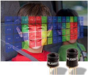 |
| Figure 2: Promotional picture of the MLX90621. |
The I2C pins of the PLC-Stamp1 are not
accessible and the Arduino Libraries for the sensor are written for the Teensy
development board. So that, I have chosen the Teensy 3.1 for reading the sensor
data and then send it through a serial port to the UART2 pins of the
PLC-Stamp1. The Teensy 3.1 is a 32 Bit Arduino-Compatible microcontroller that
it also has the Freescale MK20 controller. However, it is programmed using the
Arduino IDE instead of the CodeWarrior in the case of the PLC device. For more
information about Teensy please click here.
 |
| Figure 3: Teensy 3.1 pin-out. |
Taking the reference of a picture of the
PLC-Stamp1 datasheet:
 |
| Figure 4: An easy way to link two PLC-Stamp1s between each other and others electronic devices. |
I have though the following block scheme to
read the sensor and send the data to a computer using the powerlines of the
building.
 |
Figure 5: Block diagram of the experiment.
|
Objective
The aim of this experiment is to achieve the transmissions
of the measurements of the MLX90621 through the powerlines of the buildings and
visualizing the temperature data with a computer application.
Components
1x
Teensy 3.1 [1]
2x
PLC-STAMP1 [2]
1x
Segger J-Link EDU [4]
1x
USB-to-TTL converter [5]
2x
MicroMatch cables [6]
2x MicroMatch
vertical PCB connectors [7]
1x
Thermal Sensor MLX90621 [8]
2x Green
LED
2x
Resistors 1KΩ
1x diode 4001
2x
Resistors 4K7Ω
4x
Resistors 10KΩ
1x
Ceramic capacitor 0.01uF
1x Electrolitic
Capacitor 10uF
1x Electrolitic
Capacitor 1uF
2x Ceramic
Capacitor 0.1uF
1x
LD1117 ST LDO 3.3V
Wires…
Development of the experiment
First part: Thermal Sensor MLX90621
The first step is to do the thermal sensor work.
After looking up quite information on internet about how to connect this
sensor, I came across with the conclusion that I need a powerful
microcontroller to compute all the necessary calculations required by this
sensor in order to get the correct information of temperature. I did several
tries using an Arduino UNO and a MEGA. However, it is easier to start with
something already done. In a forum I found a previous work with the sensor
MLX90621 and the Teensy. This work can be downloaded here. This work reads the information of sensor
using the I2C bus of the Freescale MK20 controller. The data are sent to a
computer through the USB cable, where a Processing aplication draws and paints
with different colors the infrared data.
This works can also be downloaded from this
Github page:
These codes have been changed to my
purpose and are exposed in the anexe. In the next picture is shown a circuit
with the Teensy , the MLX90621, a connector to the PLC, one green LED and some
buttons.

Figure
6: Teensy3.1 with the MLX90621.
The second part: Sending data by PLC
The data transmission through the electrical
network is achieved using two PLC-Stamp1. One circuit receives the data from the sensor by his serial port and transmits them
with the Powerline Communication protocol. The other circuit receives the data
sent by PLC and then, re-sends them by his serial port to the TTL to USB
converter.
The circuit PLC-Stamp1 is a PCB designed by I2SE
and it is thought for the communication between PLC devices. This PCB uses the
communication standard Homeplug Green PHY
for PLC, which encapsules the data with TCP/IP packets and send the
information modulling the signal over the powerline.
This board can be divided in three parts in
order to understand his operation. One part is the chip Qualcomm QCA7000 who
manages the PLC communication. Another part it is the Freescale MK20DV256
microcontroller who is responsible to control the PLC chip using the SPI bus,
the peripherals components that can be connected to their GPIO and the
communication with the computer. This controller can be programmed using the
integrated development enviroment called CodeWarrior. It is necessary a
programmer. In my case, I have used the Segger J-Link-EDU. To finalize, it has
a red connector where we can access to the GPIOs, a SPI and an UART of the
microcontroller, the RESET pin of the PLC chip and the power supply pins 3V3
and GND.
The MK20 has been programmed to do the thing
described in the first paragraph. The codes are at the end of this article.
 |
| Figura 7: photo of the firsts PLC tests. |
Third part: painting the data on Windows
I have built a little circuit to get data from the UART
of the PLC-Stamp1 MicroMatch connector
and send them using a TTL to USB converter. The PLC device works with 3.3 Volts
and the TTL-USB converter ( it has the Prolific chip PL2303 ) works with 5
Volts. So, I need to convert the voltage levels of the serial communication in
order to not to damage the PLC-Stamp1.
All the data is read by the Processing application and
paints the temperature information of the 4x16 infrarred array on the screen of
the computer. This application has been
also done by the same person who did the Arduino Sketch here.
 |
| Figure 8: Screenshot of the Processing application to visualize the data of the MLX90621. |
Electric scheme of this experiment
Now, it is shown the connections among all the
used devices to trasmit the data of a thermal sensor throth the powerline to a
computer.
 |
| Figure 9: electric scheme of the MLX90621, Teensy and PLC-stamps1. |
Results
In this test I have oriented the thermal sensor
towards the door of the building. This sensor measures constantly the
temperatures. The data are read by the microcontroller and are sent to the PLC
device. The information is transmitted through the electric network of the
building. In the next picture you can see the Teensy with the MLX90621 sensor connected
to the PLC-Stamp1 and finally, this last circuit is linked to an electric plug.
The whole is powered by a portable USB-Battery. The battery powers an Arduino
which is used to provide the 3.3 volts to the PLC device. The PLC-Stamp1 gives
also the 3.3 volts using the flat cable.
 |
| Figure 10: device that reads the thermal sensor and sends it through the powerline. |
In a room of the same floor I put the PLC
receiver. This circuit receives the data of the thermal sensor, processes them
and re-sends them through the UART to the TTL to USB converter.
 |
| Figure 11: PLC device receiver conneted to the electric network and to a TTL-USB converter. |
Then, the Processing aplication read the USB port and shows the
temperature values on the screen.
Conclusion
I recommend the PLC-Stamp1 of I2SE for Powerline
Comunnications developments. Perhaps, it is a little complicated to programming
the MK20 controller using the CodeWarrior because the way of programming it is
very different to Arduino but this device works perfectly, not like the Mamba
shield.
References
[6] http://es.farnell.com/te-connectivity-amp/1483353-1/micromatch-10way-100mm/dp/1056216?ost=1056216
Appendix
In this point it is exposed the codes used in
this PLC system. It is not included some extra libraries necessaries for the
compilation of the MK20 controller, only "main.c".
Arduino code for Teensy for reading the MLX90621
#include
<Arduino.h>
#include
<i2c_t3.h>
#include
"MLX90621.h"
MLX90621
sensor; // create an instance of the Sensor class
void
setup(){
Serial.begin(9600);
Serial1.begin(9600);
pinMode(13,OUTPUT);
sensor.initialise (16); // start the thermo cam with 16 frames per second
}
void
loop()
{
String texto="";
char array[64];
memset(array,'\0',64);
digitalWrite(13,LOW);
sensor.measure(); //get new readings from the sensor
for(int y=0;y<4;y++)
{ //go through all the rows
texto.concat("[");
for(int x=0;x<16;x++){ //go through all the columns
double tempAtXY= sensor.getTemperature(y+x*4); //
extract the temperature at position x/y
texto.concat((int)tempAtXY);
if (x<15)
{
texto.concat(",");
}
}
texto.concat("]");
if (y<3)
{
texto.concat("~");
}
}
texto.concat("\n");
//Serial.print(texto);
//Serial.print(texto.length());
int firstClosingBracket= texto.indexOf('~');
int secondOpeningBracket = firstClosingBracket + 1;
String SAA=texto.substring(0,secondOpeningBracket);
SAA.toCharArray(array,SAA.length()+1);
Serial1.print(SAA);
//Serial.println(array);
delay(10);
int secondClosingBracket = texto.indexOf('~', secondOpeningBracket );
int thirdOpeningBracket = secondClosingBracket + 1;
String SBB=texto.substring(secondOpeningBracket,thirdOpeningBracket);
Serial1.print(SBB);
delay(10);
digitalWrite(13,HIGH);
int thirdClosingBracket = texto.indexOf('~', thirdOpeningBracket );
int fourthOpeningBracket = thirdClosingBracket + 1;
String SCC=texto.substring(thirdOpeningBracket,fourthOpeningBracket);
Serial1.print(SCC);
delay(10);
int fourthClosingBracket = texto.indexOf('\0', fourthOpeningBracket );
String SDD=texto.substring(fourthOpeningBracket,fourthClosingBracket);
Serial1.print(SDD);
delay(10);
}
Processing code for representing the data on the screen
/*
*
VisualizeTemperatures.pde
*
* A simple Processing
Sketch which listens to a
* Teensy 3.1+ Arduino
board connected to a Melexis 90621
* and visualizes the
temperature values measured by its
* 4x16 matrix as a
color matrix
**/
import processing.serial.*;
Serial serialConnection;
String sensorReading;
Double temperatureToString;
float[][] drawTemperatures2D;
float[][] temperatures2D;
float H, S, B;
boolean waitFirstNewline;
void setup() {
size(700, 220);
waitFirstNewline = false;
sensorReading="";
serialConnection = new
Serial(this, "COM75", 115200);
serialConnection.bufferUntil('\n');
}
void serialEvent (Serial
serialConnection) {
sensorReading =
serialConnection.readStringUntil('\n');
if (sensorReading != null) {
if
(waitFirstNewline) {
sensorReading=trim(sensorReading);
} else {
serialConnection.clear();
waitFirstNewline
= true;
}
}
}
void draw() {
background(0);
translate(35, 35);
fill(255);
noStroke();
drawTemperatures2D =
parseInput(sensorReading);
if
(drawTemperatures2D!=null) {
for (int i =
15; i >= 0; i--) {
pushMatrix();
for
(int j = 0; j < 4; j++) {
fill(getColor(((drawTemperatures2D[j][i]-37)/9)));
rect(0, 0, 30, 30);
textSize(10);
fill(0);
temperatureToString = (double) Math.round(drawTemperatures2D[j][i] * 10) / 10;
text(temperatureToString.toString(), 4, 20);
translate(0, 40);
}
popMatrix();
translate(40, 0);
}
}
}
float[][] parseInput(String input)
{
String[] temperatureRows;
temperatureRows =
input.split("~");
if (temperatureRows.length<4)
return null;
temperatures2D = new
float[temperatureRows.length][];
int i= 0;
String[] temperatureCols;
for (String row :
temperatureRows) {
row =
row.substring(1, row.length()-1);
temperatureCols
= row.split(",");
if
(temperatureCols.length<16) return null;
int j = 0;
temperatures2D[i] = new float[temperatureCols.length];
for (String col
: temperatureCols) {
try
{
temperatures2D[i][j++] = Float.parseFloat(col);
}
catch(NumberFormatException ex) {
return null;
}
}
i++;
}
return temperatures2D;
}
color getColor(float power)
{
colorMode(HSB, 1.0);
H = (1-power) * 0.4;
S = 0.9;
B = 0.9;
return color(H, S, B);
}
PLC-Stamp1 code transmitter
/**
###################################################################
** Filename
: ProcessorExpert.c
** Project
: ProcessorExpert
** Processor
: MK20DX256VLL7
** Version
: Driver 01.01
** Compiler
: GNU C Compiler
** Date/Time
: 2013-03-19, 07:47, # CodeGen: 0
** Abstract
:
** Main module.
** This module contains user's
application code.
** Settings
:
** Contents
:
** No public methods
**
** ###################################################################*/
/* MODULE ProcessorExpert */
//PLACA A!!!
/* Including needed modules to
compile this module/procedure */
#include "Cpu.h"
#include "Events.h"
#include "LED1.h"
#include "LED2.h"
#include "LED3.h"
#include "LED4.h"
#include "SM1.h"
#include "SPI_INTR.h"
#include "TIMER.h"
#include "CON_X3_6.h"
#include "CON_X3_5.h"
#include "CON_X3_4.h"
#include "CON_X3_3.h"
#include
"QCA7K_RESET.h"
#include "AS1.h"
/* Including shared modules,
which are used for whole project */
#include "PE_Types.h"
#include "PE_Error.h"
#include "PE_Const.h"
#include "IO_Map.h"
/* Librerias añadidas por mi */
#include "UART_PDD.h"
/* User includes (#include below
this line is not maintained by Processor Expert) */
#include <string.h>
#include <stdio.h>
#include "qca_spi.h"
#include "qca_block.h"
#include "libmme.h"
#include
"libmme_over_spi.h"
LDD_TDeviceData *TimerData;
LDD_TDeviceData
*spiMasterDevData;
LDD_TDeviceData *spiIntrDevData;
LDD_TDeviceData *Led1Data; /* LED1 */
LDD_TDeviceData *Led2Data; /* LED2 */
LDD_TDeviceData *Led3Data; /* LED3 */
LDD_TDeviceData *Led4Data; /* LED4 */
LDD_TDeviceData *Con_X3_3Data; /*
Ext Con X3 Pin 3 */
LDD_TDeviceData *Con_X3_4Data; /*
Ext Con X3 Pin 4 */
LDD_TDeviceData *Con_X3_5Data; /*
Ext Con X3 Pin 5 */
LDD_TDeviceData *Con_X3_6Data; /*
Ext Con X3 Pin 6 */
LDD_TDeviceData *AS1; /* Ext Con X3 Pin 7 & 8 */
LDD_TUserData *AS1_Data; /* Ext Con X3 Pin 7 & 8 */
QCASPI_DEVICE qca; // SPI driver
uint8_t sendMme; // request counter for MME
broadcast
uint8_t qcaTimeout; // counter flag for SPI driver
timeout (50 ms)
uint8_t led2Duration; // counter for LED2 ( 0 = LED off,
>0 = LED on)
uint16_t validMmeDuration; // counter for LED4 ( 0 = LED off, >0 =
LED on)
/**
* Aquí añado mis cosas
*/
uint8_t RELLENO=63;
/**
* This
function sends a mesagge to all the devices of the net with the
* information
read from the UART2.
*
@brief function to send a I2SE GPIO indication MME
*
@param libmme_config libmme structure that stores all internal settings
*
@param oda original destination address (broadcast MAC)
*
@param osa original source address (your MAC)
*
@retval >=0 the return value of libmme_over_spi_if_output function
*/
int send_uart2_reading(struct
libmme* libmme_config, uint8_t oda[LIBMME_MAC_ADDRESS_SIZE], uint8_t
osa[LIBMME_MAC_ADDRESS_SIZE], uint8_t padding[RELLENO+1])
{
uint8_t
gpioStates=0xFF;
uint8_t
gpioDirections=0xFF;
static
uint8_t mme[] = {
0x00,
0x00, 0x00, 0x00, 0x00, 0x00, // ODA [0,5]
0x00,
0x00, 0x00, 0x00, 0x00, 0x00, // OSA (variable) [6,11]
0x88,
0xE1, // MTYPE [12,13]
0x01, // MMV [14]
0x02,
0xA0, //
MMTYPE [15,16]
0x00,
0x00, // FMI [17,18]
0x00,
0x01, 0x87, // OUI [19,21]
0x00, //
MME_SUBVER [22]
0x00, // STATE
(variable) [23]
0x00, // DIR
(variable) [24]
0x00,
0x00, 0x00, 0x00, 0x00, 0x00, //[25] PADDING
0x00,
0x00, 0x00, 0x00, 0x00, 0x00, //[31]
0x00,
0x00, 0x00, 0x00, 0x00, 0x00, //[37]
0x00,
0x00, 0x00, 0x00, 0x00, 0x00, //[43]
0x00,
0x00, 0x00, 0x00, 0x00, 0x00, //[49]
0x00,
0x00, 0x00, 0x00, 0x00, 0x00, //[55]
0x00,
0x00, 0x00, 0x00, 0x00, 0x00, //[61]
0x00,
0x00, 0x00, 0x00, 0x00, 0x00, //[67]
0x00,
0x00, 0x00, 0x00, 0x00, 0x00, //[73]
0x00,
0x00, 0x00, 0x00, 0x00, 0x00, //[79]
0x00,
0x00, 0x00, 0x00, 0x00, 0x00, //[85:90]
};
struct
libmme_buffer output_data;
memcpy(&mme[0],
oda, LIBMME_MAC_ADDRESS_SIZE); // set original destination address
memcpy(&mme[6],
osa, LIBMME_MAC_ADDRESS_SIZE); // set original source address
mme[23]
= 0x3F & gpioStates;
// set GPIO states
mme[24]
= 0xC0 | gpioDirections; //
set GPIO directions
memcpy(&mme[25],
padding, sizeof(uint8_t)*(RELLENO+1)); // set original source address
output_data.data
= mme;
output_data.next
= sizeof(mme);
output_data.length
= sizeof(mme);
return
libmme_over_spi_if_output(libmme_config, &output_data); // send MME over
SPI to QCA7K
}
/**
* This
function is a replacement for libmme_over_spi_if_input to handle MMEs
*
direct without libmme.
*
*
@brief function to handle MMEs direct
*
@param netif libmme structure that stores all internal settings
*
@retval #LIBMME_OVER_SPI_RESULT_OK when MME is handled or frame is
ignored
*
@retval #LIBMME_OVER_SPI_RESULT_NULL_POINTER when netif is NULL
*
@retval #LIBMME_OVER_SPI_RESULT_RUNTIME_ERROR when actually there is not
input frame
*
@retval #LIBMME_OVER_SPI_RESULT_INVALID_PARAM when input frame is
invalid
*/
uint8_t mme_input(void *netif)
{
struct libmme* libmme_config = (struct libmme*) netif;
uint16_t receive_length = 0;
uint8_t *receive_data;
extern uint16_t validMmeDuration;
if (netif == NULL)
{
return LIBMME_OVER_SPI_RESULT_NULL_POINTER;
}
receive_data =
qcaspi_get_input_frame((QCASPI_DEVICE*)libmme_config->low_level_interface,
&receive_length);
if (receive_data == NULL)
{
return LIBMME_OVER_SPI_RESULT_RUNTIME_ERROR;
}
if (receive_length < 25) // check length
{
return LIBMME_OVER_SPI_RESULT_OK; // ignore
frame, too small length
}
if ((receive_data[12] != 0x88) ||
(receive_data[13] != 0xE1)) // check MTYPE
{
return LIBMME_OVER_SPI_RESULT_OK; // ignore
frame, unknown MTYPE
}
if (receive_data[14] != 0x01) // check MMV
{
return LIBMME_OVER_SPI_RESULT_OK; // ignore
frame, unknown MMV
}
if ((receive_data[15] != 0x02) ||
(receive_data[16] != 0xA0)) // check MMTYPE
{
return LIBMME_OVER_SPI_RESULT_OK; // ignore
frame, unknown MMTYPE
}
// ignore FMI
if ((receive_data[19] != 0x00) ||
(receive_data[20] != 0x01) ||
(receive_data[21] != 0x87)) // check I2SE OUI
{
return LIBMME_OVER_SPI_RESULT_OK; // ignore
frame, unknown OUI
}
if (receive_data[22] != 0x00) // check MME_SUBVER
{
return LIBMME_OVER_SPI_RESULT_INVALID_PARAM;
// invalid MME_SUBVER
}
if (receive_data[23] & 0xC0) // check STATE
{
return LIBMME_OVER_SPI_RESULT_INVALID_PARAM;
// invalid STATE
}
if ((receive_data[24] & 0xC0) != 0xC0) // check DIR
{
return LIBMME_OVER_SPI_RESULT_INVALID_PARAM;
// invalid DIR
}
if (receive_data[25] =='[') // check confirmation parameter
CON_X3_4_ToggleFieldBits(Con_X3_4Data,
Con_X3_4Pin, 1);//Put HIGH GPIO4
else
CON_X3_4_ClearFieldBits(Con_X3_4Data,
Con_X3_4Pin, 1);//Put LOW GPIO4
validMmeDuration = 1; // switch LED4 on
return LIBMME_OVER_SPI_RESULT_OK;
}
/************************************************************************************
*
*
@brief function to enable all interrupts
*
************************************************************************************/
void enableInt(void)
{
__EI();
}
/************************************************************************************
*
*
@brief function to disable all interrupts
*
************************************************************************************/
void disableInt(void)
{
__DI();
}
/*lint -save -e970 Disable MISRA rule (6.3) checking. */
int main(void)
/*lint -restore Enable MISRA rule
(6.3) checking. */
{
uint8_t
originalDstAddr[6] = { 0xFF, 0xFF, 0xFF, 0xFF, 0xFF, 0xFF }; // broadcast
address
/*
Please replace with MAC hardware address MK20 on the PLC-Stamp 1 label. */
uint8_t
originalSrcAddr[6] = { 0x00, 0x01, 0x87, 0x04, 0x05, 0x8B };//PLC-Stamp A
uint32_t
ticks;
uint8_t
i;
struct
libmme libmme_config;
int
result;
uint8_t
data[RELLENO+1];
uint8_t
InputBuffer[RELLENO];
memset
(data,'\0',sizeof(data));
memset
(InputBuffer,'\0',sizeof(InputBuffer));
/***
Processor Expert internal initialization. DON'T REMOVE THIS CODE!!! ***/
PE_low_level_init();
/***
End of Processor Expert internal initialization. ***/
/*
Init all 4 LEDs */
Led1Data
= LED1_Init(NULL);
Led2Data
= LED2_Init(NULL);
Led3Data
= LED3_Init(NULL);
Led4Data
= LED4_Init(NULL);
/*
Init GPIOs on external connector X3 */
Con_X3_3Data
= CON_X3_3_Init(NULL);
Con_X3_4Data
= CON_X3_4_Init(NULL);
Con_X3_5Data
= CON_X3_5_Init(NULL);
Con_X3_6Data
= CON_X3_6_Init(NULL);
spiMasterDevData
= SM1_Init(&qca); // Init spi
master interface with pointer to the driver
spiIntrDevData
= SPI_INTR_Init(&qca); // Init spi interrupt gpio with pointer to the
driver
/*
Init SPI driver with attribute set 0 (default: Width = 8 bit, MSB first,
CPOL=1, CPHA=1, No parity, No CS toggle)
* and chip 0 (chip select = active low) */
qcaspi_init(&qca,
spiMasterDevData, // spi master device
spiIntrDevData, // spi interrupt gpio device
SpiIntr, // spi interrupt gpio number
SM1_ReceiveBlock, // pointer to spi receive function
SM1_SendBlock, // pointer to spi send function
SM1_SelectConfiguration, // pointer to spi config function
SPI_INTR_GetFieldValue, // pointer to get level of spi interrupt
disableInt, // pointer to disable all
interrupts
enableInt); // pointer to enable all
interrupts
libmme_init(&libmme_config,
&qca, libmme_over_spi_if_output, NULL, NULL);
libmme_over_spi_if_init(&libmme_config);
qcaspi_set_interface(&qca,
&libmme_config);
qcaspi_set_interface_input(&qca,
mme_input); // use custom frame input function instead from libmme_over_spi
//Aviso
luminoso de que la placa se esta inicializando
for
(i = 0; i < 10; i++)
{
/* Switch all LEDs on */
LED1_ClearFieldBits(Led1Data, Led1Pin, 1);
LED2_ClearFieldBits(Led2Data, Led2Pin, 1);
LED3_ClearFieldBits(Led3Data, Led3Pin, 1);
LED4_ClearFieldBits(Led4Data, Led4Pin, 1);
CON_X3_4_SetFieldBits(Con_X3_4Data,
Con_X3_4Pin, 1);//Put HIGH GPIO4
for (ticks = 0; ticks < 2000000;)
{
ticks++;
}
/* Switch all LEDs off */
LED1_SetFieldBits(Led1Data, Led1Pin, 1);
LED2_SetFieldBits(Led2Data, Led2Pin, 1);
LED3_SetFieldBits(Led3Data, Led3Pin, 1);
LED4_SetFieldBits(Led4Data, Led4Pin, 1);
CON_X3_4_ClearFieldBits(Con_X3_4Data,
Con_X3_4Pin, 1);//Put LOW GPIO4
for (ticks = 0; ticks < 2000000;)
{
ticks++;
}
}
/*
Start timer (interval = 50 ms) */
TimerData
= TIMER_Init(&qca);
AS1=AS1_Init(AS1_Data);//Inicializa
el puerto serie
/*
application main loop */
while
(1)
{
if
(qcaTimeout > 0)
{
qcaTimeout--;
sendMme++;
}
if
(qcaspi_is_sync(&qca))// If synchronisation is ready, switch on LED3
LED3_ClearFieldBits(Led3Data,
Led3Pin, 1);
else
LED3_SetFieldBits(Led3Data,
Led3Pin, 1);
(void)
qcaspi_process(&qca); // async spi task
if
((sendMme > 0) && qcaspi_is_sync(&qca))
{
if(AS1_ReceiveBlock(AS1,InputBuffer,
sizeof(InputBuffer))==ERR_OK)//TODO
{
LED1_ToggleFieldBits(Led1Data,
Led1Pin, 1);
memcpy(
&data[0], InputBuffer, sizeof(InputBuffer) );
result
= send_uart2_reading(&libmme_config,originalDstAddr,originalSrcAddr,data);
if
(result == LIBMME_OVER_SPI_RESULT_OK)
{
led2Duration
= 1; // switch LED2 on
sendMme--;
}
}
}
}
/*** Don't write any code pass this line, or it will be deleted during
code generation. ***/
/*** RTOS startup code. Macro PEX_RTOS_START is defined by the RTOS
component. DON'T MODIFY THIS CODE!!! ***/
#ifdef PEX_RTOS_START
PEX_RTOS_START(); /* Startup of the selected
RTOS. Macro is defined by the RTOS component. */
#endif
/*** End of RTOS startup code.
***/
/*** Processor Expert end of main routine. DON'T MODIFY THIS CODE!!!
***/
for(;;){}
/*** Processor Expert end of main routine. DON'T WRITE CODE BELOW!!!
***/
} /*** End of main routine. DO
NOT MODIFY THIS TEXT!!! ***/
/* END ProcessorExpert */
/*
**
###################################################################
**
** This file was created by Processor Expert
10.0 [05.03]
** for the Freescale Kinetis series of
microcontrollers.
**
**
###################################################################
*/
PLC-Stamp1 receiver
/**
###################################################################
** Filename
: ProcessorExpert.c
** Project
: ProcessorExpert
** Processor
: MK20DX256VLL7
** Version
: Driver 01.01
** Compiler
: GNU C Compiler
** Date/Time
: 2013-03-19, 07:47, # CodeGen: 0
** Abstract
:
** Main module.
** This module contains user's
application code.
** Settings
:
** Contents
:
** No public methods
**
**
**
###################################################################*/
/*
MODULE ProcessorExpert */
//PLACA
B!!!
/*
Including needed modules to compile this module/procedure */
#include
"Cpu.h"
#include
"Events.h"
#include
"LED1.h"
#include
"LED2.h"
#include
"LED3.h"
#include
"LED4.h"
#include
"SM1.h"
#include
"SPI_INTR.h"
#include
"TIMER.h"
#include
"CON_X3_6.h"
#include
"CON_X3_5.h"
#include
"CON_X3_4.h"
#include
"CON_X3_3.h"
#include
"QCA7K_RESET.h"
#include
"AS1.h"
/*
Including shared modules, which are used for whole project */
#include
"PE_Types.h"
#include
"PE_Error.h"
#include
"PE_Const.h"
#include
"IO_Map.h"
#include
"UART_PDD.h"
/*
User includes (#include below this line is not maintained by Processor Expert)
*/
#include
<string.h>
#include
<stdio.h>
#include
"qca_spi.h"
#include
"qca_block.h"
#include
"libmme.h"
#include
"libmme_over_spi.h"
LDD_TDeviceData
*TimerData;
LDD_TDeviceData
*spiMasterDevData;
LDD_TDeviceData
*spiIntrDevData;
LDD_TDeviceData
*Led1Data; /* LED1 */
LDD_TDeviceData
*Led2Data; /* LED2 */
LDD_TDeviceData
*Led3Data; /* LED3 */
LDD_TDeviceData
*Led4Data; /* LED4 */
LDD_TDeviceData
*Con_X3_3Data; /* Ext Con X3 Pin 3 */
LDD_TDeviceData
*Con_X3_4Data; /* Ext Con X3 Pin 4 */
LDD_TDeviceData
*Con_X3_5Data; /* Ext Con X3 Pin 5 */
LDD_TDeviceData
*Con_X3_6Data; /* Ext Con X3 Pin 6 */
LDD_TDeviceData
*AS1;
LDD_TUserData *AS1_Data;
QCASPI_DEVICE
qca; // SPI driver
uint8_t
sendMme; // request counter
for MME broadcast
uint8_t
qcaTimeout; // counter flag
for SPI driver timeout (50 ms)
uint8_t led2Duration; // counter for LED2 ( 0 = LED off,
>0 = LED on)
uint16_t
validMmeDuration; // counter for LED4
( 0 = LED off, >0 = LED on)
/**
* Aquí añado mis cosas
*/
uint8_t
RELLENO=64,tramaRecibida=0;
/**
* This
function sends a confirmation message
*
*
@brief function to send a I2SE GPIO indication MME
*
@param libmme_config libmme structure that stores all internal settings
*
@param oda original destination address (broadcast MAC)
*
@param osa original source address (your MAC)
*
@param gpioDirections GPIO directions of the last 6 connector pins (0 =
input / 1 = output)
*
@param gpioStates last 6 levels of the GPIO pins as flags (0 = low, 1 =
high)
*
@retval >=0 the return value of libmme_over_spi_if_output function
*/
int
send_confirmation(struct libmme* libmme_config, uint8_t
oda[LIBMME_MAC_ADDRESS_SIZE], uint8_t osa[LIBMME_MAC_ADDRESS_SIZE])
{
uint8_t gpioStates=0xFF;
uint8_t gpioDirections=0xFF;
static uint8_t mme[] = {
0x00, 0x00, 0x00, 0x00, 0x00,
0x00, // ODA [0,5]
0x00, 0x00, 0x00, 0x00, 0x00,
0x00, // OSA (variable) [6,11]
0x88, 0xE1, // MTYPE [12,13]
0x01, // MMV [14]
0x02, 0xA0, // MMTYPE [15,16]
0x00, 0x00, // FMI [17,18]
0x00, 0x01, 0x87, // OUI [19,21]
0x00, //
MME_SUBVER [22]
0x00, // STATE
(variable) [23]
0x00, // DIR
(variable) [24]
'[', 0x00, 0x00, 0x00, 0x00,
0x00,
0x00, 0x00, 0x00, 0x00, 0x00,
0x00,
0x00, 0x00, 0x00, 0x00, 0x00,
0x00,
0x00, 0x00, 0x00, 0x00, 0x00,
0x00,
0x00, 0x00, 0x00, 0x00, 0x00,
0x00,
0x00, 0x00, 0x00, 0x00,
0x00 // Padding [25,59]
};
struct libmme_buffer output_data;
memcpy(&mme[0], oda,
LIBMME_MAC_ADDRESS_SIZE); // set original destination address
memcpy(&mme[6], osa,
LIBMME_MAC_ADDRESS_SIZE); // set original source address
mme[23] = 0x3F & gpioStates; // set GPIO states
mme[24] = 0xC0 | gpioDirections; // set GPIO directions
output_data.data = mme;
output_data.next = sizeof(mme);
output_data.length = sizeof(mme);
return
libmme_over_spi_if_output(libmme_config, &output_data); // send MME over
SPI to QCA7K
}
/**
* This
function is a replacement for libmme_over_spi_if_input to handle MMEs
*
direct without libmme.
*
*
@brief function to handle MMEs direct
*
@param netif libmme structure that stores all internal settings
*
@retval #LIBMME_OVER_SPI_RESULT_OK when MME is handled or frame is
ignored
*
@retval #LIBMME_OVER_SPI_RESULT_NULL_POINTER when netif is NULL
*
@retval #LIBMME_OVER_SPI_RESULT_RUNTIME_ERROR when actually there is not
input frame
*
@retval #LIBMME_OVER_SPI_RESULT_INVALID_PARAM when input frame is
invalid
*/
uint8_t
mme_input(void *netif)
{
struct libmme* libmme_config = (struct
libmme*) netif;
uint16_t receive_length = 0;
uint8_t *receive_data;
extern uint16_t validMmeDuration;
if (netif == NULL)
{
return LIBMME_OVER_SPI_RESULT_NULL_POINTER;
}
receive_data =
qcaspi_get_input_frame((QCASPI_DEVICE*)libmme_config->low_level_interface,
&receive_length);
if (receive_data == NULL)
{
return LIBMME_OVER_SPI_RESULT_RUNTIME_ERROR;
}
if (receive_length < 25) // check length
{
return LIBMME_OVER_SPI_RESULT_OK; // ignore frame, too small length
}
if ((receive_data[12] != 0x88) ||
(receive_data[13] != 0xE1)) // check MTYPE
{
return LIBMME_OVER_SPI_RESULT_OK; // ignore frame, unknown MTYPE
}
if (receive_data[14] != 0x01) // check MMV
{
return LIBMME_OVER_SPI_RESULT_OK; // ignore frame, unknown MMV
}
if ((receive_data[15] != 0x02) ||
(receive_data[16] != 0xA0)) // check MMTYPE
{
return LIBMME_OVER_SPI_RESULT_OK; // ignore frame, unknown MMTYPE
}
// ignore FMI
if ((receive_data[19] != 0x00) ||
(receive_data[20] != 0x01) ||
(receive_data[21] != 0x87)) // check I2SE OUI
{
return LIBMME_OVER_SPI_RESULT_OK; // ignore frame, unknown OUI
}
if (receive_data[22] != 0x00) // check
MME_SUBVER
{
return LIBMME_OVER_SPI_RESULT_INVALID_PARAM; // invalid MME_SUBVER
}
if (receive_data[23] & 0xC0) // check
STATE
{
return LIBMME_OVER_SPI_RESULT_INVALID_PARAM; // invalid STATE
}
if ((receive_data[24] & 0xC0) != 0xC0) //
check DIR
{
return LIBMME_OVER_SPI_RESULT_INVALID_PARAM;
// invalid DIR
}
uint8_t *mensaje = receive_data + 25;
AS1_SendBlock(AS1,mensaje,sizeof(uint8_t)*strlen(mensaje));
tramaRecibida=1;
validMmeDuration = 1; // switch LED4 on
return LIBMME_OVER_SPI_RESULT_OK;
}
/************************************************************************************
*
*
@brief function to enable all interrupts
*
************************************************************************************/
void
enableInt(void)
{
__EI();
}
/************************************************************************************
*
*
@brief function to disable all interrupts
*
************************************************************************************/
void
disableInt(void)
{
__DI();
}
int
main(void)
{
uint8_t originalDstAddr[6] = { 0xFF,
0xFF, 0xFF, 0xFF, 0xFF, 0xFF }; // broadcast address
/* Please replace with MAC hardware
address MK20 on the PLC-Stamp 1 label. */
uint8_t originalSrcAddr[6] = { 0x00,
0x01, 0x87, 0x04, 0x05, 0x87 };//PLC-Stamp B
uint32_t ticks;
uint8_t i;
struct libmme libmme_config;
int result;
/*** Processor Expert internal
initialization. DON'T REMOVE THIS CODE!!! ***/
PE_low_level_init();
/*** End of Processor Expert internal
initialization. ***/
/* Init all 4 LEDs */
Led1Data = LED1_Init(NULL);
Led2Data = LED2_Init(NULL);
Led3Data = LED3_Init(NULL);
Led4Data = LED4_Init(NULL);
/* Init GPIOs on external connector X3
*/
Con_X3_3Data = CON_X3_3_Init(NULL);
Con_X3_4Data = CON_X3_4_Init(NULL);
Con_X3_5Data = CON_X3_5_Init(NULL);
Con_X3_6Data = CON_X3_6_Init(NULL);
spiMasterDevData =
SM1_Init(&qca); // Init spi master
interface with pointer to the driver
spiIntrDevData =
SPI_INTR_Init(&qca); // Init spi interrupt gpio with pointer to the driver
/* Init SPI driver with attribute set 0
(default: Width = 8 bit, MSB first, CPOL=1, CPHA=1, No parity, No CS toggle)
*
and chip 0 (chip select = active low) */
qcaspi_init(&qca,
spiMasterDevData, // spi master device
spiIntrDevData, // spi interrupt gpio device
SpiIntr, // spi interrupt gpio number
SM1_ReceiveBlock, // pointer to spi receive function
SM1_SendBlock, // pointer to spi send function
SM1_SelectConfiguration, // pointer to spi config function
SPI_INTR_GetFieldValue, // pointer to get level of spi interrupt
disableInt, // pointer to disable all
interrupts
enableInt); // pointer to enable all
interrupts
libmme_init(&libmme_config,
&qca, libmme_over_spi_if_output, NULL, NULL);
libmme_over_spi_if_init(&libmme_config);
qcaspi_set_interface(&qca,
&libmme_config);
qcaspi_set_interface_input(&qca,
mme_input); // use custom frame input function instead from libmme_over_spi
for (i = 0; i < 10; i++)
{
/* Switch all LEDs on */
LED1_ClearFieldBits(Led1Data, Led1Pin, 1);
LED2_ClearFieldBits(Led2Data, Led2Pin, 1);
LED3_ClearFieldBits(Led3Data, Led3Pin, 1);
LED4_ClearFieldBits(Led4Data, Led4Pin, 1);
CON_X3_6_SetFieldBits(Con_X3_6Data, Con_X3_6Pin, 1);//Put HIGH GPIO6
for (ticks = 0; ticks < 2000000;)
{
ticks++;
}
/* Switch all LEDs off */
LED1_SetFieldBits(Led1Data, Led1Pin, 1);
LED2_SetFieldBits(Led2Data, Led2Pin, 1);
LED3_SetFieldBits(Led3Data, Led3Pin, 1);
LED4_SetFieldBits(Led4Data, Led4Pin, 1);
CON_X3_6_ClearFieldBits(Con_X3_6Data, Con_X3_6Pin, 1);//Put LOW GPIO6
for (ticks = 0; ticks < 2000000;)
{
ticks++;
}
}
/* Start timer (interval = 50 ms) */
TimerData = TIMER_Init(&qca);
AS1=AS1_Init(AS1_Data);
/* application main loop */
while (1)
{
/* poll every 50 ms DIP
switches and GPIOs */
if (qcaTimeout > 0)
{
qcaTimeout--;
sendMme++;
}
if (qcaspi_is_sync(&qca))
LED3_ClearFieldBits(Led3Data,
Led3Pin, 1);
else
LED3_SetFieldBits(Led3Data,
Led3Pin, 1);
(void) qcaspi_process(&qca);
// async spi task
if ((sendMme > 0) &&
qcaspi_is_sync(&qca))
{
if(tramaRecibida==1)
{
result =
send_confirmation(&libmme_config,originalDstAddr,originalSrcAddr); //
broadcast MME
if (result ==
LIBMME_OVER_SPI_RESULT_OK)
{
sendMme--;
led2Duration
= 1; // switch LED2 on
}
tramaRecibida=0;
}
}
}
/*** Don't write any code pass this line, or
it will be deleted during code generation. ***/
/*** RTOS startup code. Macro PEX_RTOS_START
is defined by the RTOS component. DON'T MODIFY THIS CODE!!! ***/
#ifdef PEX_RTOS_START
PEX_RTOS_START(); /* Startup of the selected
RTOS. Macro is defined by the RTOS component. */
#endif
/*** End of RTOS startup code. ***/
/*** Processor Expert end of main routine.
DON'T MODIFY THIS CODE!!! ***/
for(;;){}
/*** Processor Expert end of main routine.
DON'T WRITE CODE BELOW!!! ***/
}
/*** End of main routine. DO NOT MODIFY THIS TEXT!!! ***/
/*
END ProcessorExpert */
/*
**
###################################################################
**
** This file was created by Processor Expert
10.0 [05.03]
** for the Freescale Kinetis series of
microcontrollers.
**
**
###################################################################
*/