Controlling 32 relays
ABSTRACT
The aim of this project is to control 32 relays with
an Android tablet. The Android
application sends a message to an Arduino Mega by Bluetooth. Arduino receives
the Bluetooth message thanks to a HC-06 Bluetooth device. Arduino decodes the
messages and then, activates or deactivates the relays. The period of time of
the activation of the relays depends on the value selected in the Android
application. The app has 32 sliders for selecting the activation time of the
relays.
 |
|
Figure 1: Image of the relays
|
COMPONENTS
1 x Samsung
Galaxy Tab 10.1’’ with Android 3.1
1 x Arduino
Mega
2 x Modules of 16 relays
1 x Module Bluetooth
HC-06
1 x Wires
DEVELOPMENT
This project is part
of a bigger one but in this blog I will only explain the part of controlling
the 32 relays by Bluetooth.
The Bluetooth device
is connected to the Arduino using the Serial port 3. These pins are 14 for TX3
and 15 for RX3.
 |
|
Figure 2: HC-06 Bluetooth Module
|
Each relay module has
16 male pins for connecting to the Arduino. Also, it has one pin for GND and
another for +5V. Moreover, the board has a block for powering the relay module
with a higher volts supply. In this case, 12V
are provided by a power supply connected to the electrical network.
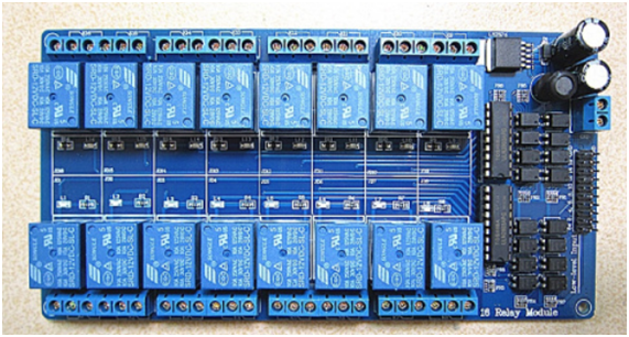 |
Figure
3: Module with 16 relays optoacoppler
|
I’ve used the digital
Arduino outputs from 22 to 53 for
connecting the two relays boards to the Arduino Mega.
 |
Figure 4: Arduino Mega digital pins used for connecting
the two relay boards.
|
The following picture
shows how the components must be connected among them.
 |
|
Figure 5: Schematic of Arduino Mega with the relay and
Bluetooth modules
|
The Android
app is connected to the HC-06 Bluetooth module automatically. Then, I select
the time of period that the relays are activated. There is a slider for each
relay. Also, I can select the timeline sliders to indicate the maximum time the
relay can be activated. After that, if the Bluetooth connection is ready, you
can press the "Send Text" to transmit a 32-character string button.
The data string has the following format:
String dataToSend={‘E’,’:’,0x01,0x02,0x03,0x04,0x05,0x06,0x07,0x08,0x09,0x0A,0x0B,0x0C,0x0D,0x0E,0x0F,0x10,0x11,0x12,0x13,0x14,0x15,0x16,0x17,0x18,0x19,0x1A,0x1B,0x1C,0x1D,0x1E,0x1F,0x20,0x21,0x22,0x23,0x24,0x25,0x26,0x27,0x28,0x29,0x2A,0x2B,0x2C,0x2D,0x2E,0x2F,0x30,0x31,0x32,’.’};
The total size of the string is 35 bytes. The
first character always is an ‘E’, the second is ‘:’ and the last is ‘.’. The
bytes in middle of these characters are the values of time which the relays
will be activate. These values are represented in hexadecimal.
At the beginning of
this project, I wanted to send the time of the relays with integer format.
However, I discovered that the Arduino Serial port has a maximum buffer of 64
bytes. So, if I sent 32 numbers in integer, I will need more than 64 bytes
because the ‘int’ format need at least 2 bytes. We can check this easily with
Arduino writing something like this:
int timeRelays[]={100,40,3,4};//an array of 4
integers Sizeof(timeRelays);//64
So, the reason why
I decided not to sent the data in integer format, it is that the packet to
transmit must be less than 64 bytes.
Arduino Mega
receives the data through SPP thanks to
the HC-06 Bluetooth module. These data are saved in variable type String. Then,
the string of characters are decoded and the values of time for the relays are
stored in an array of integers. The array’s size is 32 integers, one integer
for each relay.
After getting the
time for each relay, I found the problem
of how manage 32 outputs simultaneously. The solution that I adopted was to use
the Timer library coded by Simon Monk [3]. This library can be easily
downloaded from [4]. I had to modify some lines of the library for my purpose.
In the file Timer.h, I changed the line:
#define
MAX_NUMBER_OF_EVENTS (10) to #define MAX_NUMBER_OF_EVENTS (32)
Furthermore, I made a new method based on the method timer::oscillate
described in the file Timer.cpp. My method is called timer::halfPulse. The only difference respect to the other method is that the variable repeatCount is always 1 because I only
wanted a transition, not a full cycle.
 |
| Figure 6: Android application without Bluetooth connection. |
 |
| Figure 7: Android application connected to the Arduino. |
RESULTS
The Arduino code used in this Project does the
following:
1- Initializes the Serial Ports 1 and 3. Sets up the
Bluetooth and configures the digital outputs.
2- Arduino makes blinking the Digital Outputs
connected to the relays, in order to test if they all work properly. In my
case, one relay is damaged.
3-Once the Bluetooth connection is established between
the Android tablet and the HC-06 module, the program waits to receive messages.
The messages are parsed and if the data is received correctly, Arduino will
activate the relays during an interval of time.
The next video shows how the code works:
REFERENCES
OTHER PROPOSAL WITH
RELAYS
Instead of using an
Arduino Mega for controlling all the relays, I would like to use an Arduino Uno
for managing the 32 relays. I think that
this idea is possible if I use two 16-channel
Analog Multiplexers like the 74HC4067N. This IC need 4 digital outputs an one
analog input. I’ve designed the circuit using Eagle. The schematic is the
following:
 |
Figure
6: Atmega328 with two multiplexers for controlling 32 relays by Bluetooth.
|
APPENDIX
Arduino code:
#include
<Event.h>
#include
<Timer.h>
/*
* * * * * * * * * * * * * * * * * * * * * * * * * * * *
* Timer library coded by Simon Monk
* Timer.h has been downloaded from this link:
http://www.simonmonk.org
* I've modified the parameter :
MAX_NUMBER_OF_EVENTS (10) by #define MAX_NUMBER_OF_EVENTS (32)
* Furthermore, I've created a new method from
the Oscillate method
+ This new function is called: half-pulse. The
unique difference respect to the Oscillate method is: repeatCount=1
*
* * * * * * * * * * * * * * * * * * * * * * * * * * * */
//Digital
outputs connected to the relays
#define
EV_32 22
#define
EV_31 23
#define
EV_30 24
#define
EV_29 25
#define
EV_28 26
#define
EV_27 27
#define
EV_26 28
#define
EV_25 29
#define
EV_24 30
#define
EV_23 31
#define
EV_22 32
#define
EV_21 33
#define
EV_20 34
#define
EV_19 35
#define
EV_18 36
#define
EV_17 37
#define
EV_16 38
#define
EV_15 39
#define
EV_14 40
#define
EV_13 41
#define
EV_12 42
#define
EV_11 43
#define
EV_10 44
#define
EV_9 45
#define
EV_8 46
#define
EV_7 47
#define
EV_6 48
#define
EV_5 49
#define
EV_4 50
#define
EV_3 51
#define
EV_2 52
#define
EV_1 53
//Functions
used in this skecth
//Bluetooth
void SetupBT(void);
void readAnswer(void);
boolean ReceivingMessages(void);
//Relays
void SetupRelays(void);
void TestRelays (void);
Timer
t;
int
relayIntervals[32];
void
setup()
{
Serial.begin(9600);
SetupRelays();
TestRelays();
SetupBT();
}
void
loop()
{
t.update();
if (ReceivingMessages() == true)
{
Serial.println("Interval times for the
32 relays:");
for (uint8_t n = 0; n < 32; n++)
{
Serial.print("[");
Serial.print(n + 1); Serial.print("]: ");
Serial.print(relayIntervals[n]);
Serial.print(" "); Serial.println(53 - n);
if (relayIntervals[n] > 0)
t.halfPulse(53 - n, relayIntervals[n] * 1000, LOW);
else digitalWrite(53 - n, HIGH); activa
}//If the value is 0, the relays is
deactivated with a high pulse
}
delay(1000);
}
/**************************************
*Configuration
of the Bluetooth Module*
***************************************/
void
SetupBT(void)
{
Serial3.begin(9600);
delay(100);
Serial.println("Initializing the
Bluetooth, wait a moment please...");
Serial3.print("AT");
readAnswer();
Serial.println("ResetingBluetooth");
Serial3.print("AT+RESET");
readAnswer();
Serial.println("Bluetooth Version
");
Serial3.print("AT+VERSION");
readAnswer();
Serial.println("Nombre: RELAYS");
Serial3.print("AT+NAMERELAYS");
readAnswer();
Serial.println("9600 Bauds");
Serial3.print("AT+BAUD4");
readAnswer();
Serial.println("Pin: 1234");
Serial3.print("AT+PIN1234");
readAnswer();
Serial.println("Configuration
finished.");
}
/*****************************************************************
*
Reads the answer of the bluetooth module from the serial port 3*
******************************************************************/
void
readAnswer(void)
{
delay(1000);
if(Serial3.available())
{
do
{
Serial.print((char) Serial3.read());
}while(Serial3.available()>0);
}
Serial.println("\n");
}
boolean
ReceivingMessages(void)
{
String trama="";
boolean state=false;
if(Serial3.available())//Wait until
something is writen in the serial port
{
delay(100);
while(Serial3.available()>0) trama.concat((char)Serial3.read());
Serial.println(trama.length());
if(trama.length()==35)
{
Serial.print(trama.charAt(0));
Serial.print(trama.charAt(1));
for(uint8_t
i=2;i<trama.length()-1;i++)
{
relayIntervals[i-2]=(int)trama.charAt(i);
Serial.print(relayIntervals[i-2]);
if(i==trama.length()-2)
Serial.print("");
else Serial.print(',');
}
Serial.println(trama.charAt(trama.length()-1));
return state=true;
}
else
{
Serial.println(trama);
return state=false;
}
}
}
/*******************************************************************************
* Configuration of the digital outputs for
activate and deactivate the relays *
*******************************************************************************/
void
SetupRelays(void)
{
pinMode(EV_1, OUTPUT);
pinMode(EV_2, OUTPUT);
pinMode(EV_3, OUTPUT);
pinMode(EV_4, OUTPUT);
pinMode(EV_5, OUTPUT);
pinMode(EV_6, OUTPUT);
pinMode(EV_7, OUTPUT);
pinMode(EV_8, OUTPUT);
pinMode(EV_9, OUTPUT);
pinMode(EV_10, OUTPUT);
pinMode(EV_11, OUTPUT);
pinMode(EV_12, OUTPUT);
pinMode(EV_13, OUTPUT);
pinMode(EV_14, OUTPUT);
pinMode(EV_15, OUTPUT);
pinMode(EV_16, OUTPUT);
pinMode(EV_17, OUTPUT);
pinMode(EV_18, OUTPUT);
pinMode(EV_19, OUTPUT);
pinMode(EV_20, OUTPUT);
pinMode(EV_21, OUTPUT);
pinMode(EV_22, OUTPUT);
pinMode(EV_23, OUTPUT);
pinMode(EV_24, OUTPUT);
pinMode(EV_25, OUTPUT);
pinMode(EV_26, OUTPUT);
pinMode(EV_27, OUTPUT);
pinMode(EV_28, OUTPUT);
pinMode(EV_29, OUTPUT);
pinMode(EV_30, OUTPUT);
pinMode(EV_31, OUTPUT);
pinMode(EV_32, OUTPUT);
//For security matters, all the relays are
opened
digitalWrite(EV_1, HIGH);
digitalWrite(EV_2, HIGH);
digitalWrite(EV_3, HIGH);
digitalWrite(EV_4, HIGH);
digitalWrite(EV_5, HIGH);
digitalWrite(EV_6, HIGH);
digitalWrite(EV_7, HIGH);
digitalWrite(EV_8, HIGH);
digitalWrite(EV_9, HIGH);
digitalWrite(EV_10, HIGH);
digitalWrite(EV_11, HIGH);
digitalWrite(EV_12, HIGH);
digitalWrite(EV_13, HIGH);
digitalWrite(EV_14, HIGH);
digitalWrite(EV_15, HIGH);
digitalWrite(EV_16, HIGH);
digitalWrite(EV_17, HIGH);
digitalWrite(EV_18, HIGH);
digitalWrite(EV_19, HIGH);
digitalWrite(EV_20, HIGH);
digitalWrite(EV_21, HIGH);
digitalWrite(EV_22, HIGH);
digitalWrite(EV_23, HIGH);
digitalWrite(EV_24, HIGH);
digitalWrite(EV_25, HIGH);
digitalWrite(EV_26, HIGH);
digitalWrite(EV_27, HIGH);
digitalWrite(EV_28, HIGH);
digitalWrite(EV_29, HIGH);
digitalWrite(EV_30, HIGH);
digitalWrite(EV_31, HIGH);
digitalWrite(EV_32, HIGH);
Serial.println("The configuration of the
digital outputs for the relays is finished.");
}
/*************************************************************************************************
*This
function opens and closes all the relays sequentially in order to test if they
work or not. *
**************************************************************************************************/
void
TestRelays(void)
{
for(int i=54;i>21;i--)
{
digitalWrite(i,HIGH);
delay(100);
digitalWrite(i,LOW);
delay(200);
digitalWrite(i,HIGH);
delay(100);
}
}