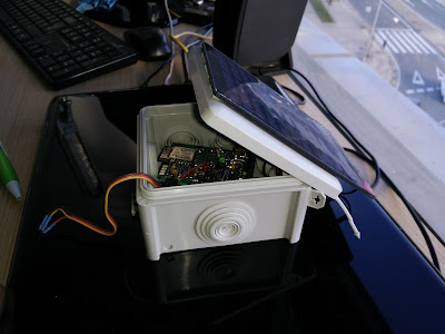
BATTERY
LOGGER
INTRODUCTION
This
circuit reads the battery volt level and saves the information in the
web platform ThinkSpeak. The data is sent to internet through a wifi
connection sets
thank to the module
ESP-12 with the ESP8266 chip. This
module can be programed using the Arduino IDE and it has several
digital pins, one analog input, UART, WiFi connectivity,
etc. For more information about this module, you can visit these webs
which helps me to understand how ESP-12 works:
This
device has a little 350mAh LiPo battery. It can be recharged using a
uart-to-ttl converter like mine microUSBProgramming adaptor or using the solar energy with a photovoltaic
panel.
The
component who manages the battery charging is the MCP73831.
The
code is based on the “WriteVoltage” example of the library
Thingspeak. There is a lot of information here:
https://thingspeak.com/
My
first intention was to upload the information of a temperature
sensor, however I needed to know how many time could this device keep
working using only the solar energy. For this reason I adapted the
circuit to read the battery level instead of the temperature. In the
next picture you can see the circuit with a temperature sensor
connected to the analog input.
COMPONENTS
1 x
ESP12 module
1
x MCP73831IT-2DCI/OT linear
charge management controller
1
x LM1117DT-3.3/NOPB
1
x 6V Photovoltaic solar cell
2
x 1N4148
1
x slide switch
2
x push button
1
x 350 mAh LiPo Battery
1
x green led
1
x red led
1
x 10uF electrolitic capacitor
2
x 0.1uF tantalum capacitor
2
x 4.7uF capacitor
5
x 10K resistor
1
x 33K resistor
1
x 2K resistor
2
x 680 resistor
1
x prototipyng board
pins
, solder tin, wires...
DESIGN
This
design has been built in a little perforated prototyping board.I
have mixed conventional and smd components. I always used what I have
in stock in order to not spend money :).
The
design is based on the NodeMCU circuit which has the same ESP-12
module:
Basically
I have added the battery management and I
have used
an external USB adaptor. The schematic of the circuit is below:
The
ESP-12 analog input reads voltages between 0 and 1 volt. It is
necessary to convert the volt levels of the battery. Normally, the
battery levels are between 3.5V and 4.3 volts when it is charging.
So, the volt divider is made with two resistor, one of 33K and
another of 10K, the equation is the following:
ADC=(Vbat+R6)/(R9+R6)=(4.3+10K)/(33K+10K)=1V
The
USB-adaptor used is designed to not damaged circuits that work with
3.3V. It has the FTDI chip FT232R. The two diodes 1N4148 are advised
by the manufactured.
How
the code works? The device is switch on with the slide switch. The
WiFi connectivity begins and the ESP-12 tries to connect with the
Thinkspeak Platform. The battery volts level is read and send to the
ThinkSpeak channel. Then, the microcontroller falls into sleep during
one hour. After this period of time the controller wakes up itself
and the code begins again. Meanwhile, the battery is charging if the
photovoltaic panel has sunlight.
The design of the circuit has a red LED connected to the GPIO0 of the ESP-12 module, however it is always switched off in order to saving energy.
The design of the circuit has a red LED connected to the GPIO0 of the ESP-12 module, however it is always switched off in order to saving energy.
RESULTS
The
results can be seen here: https://thingspeak.com/channels/82736. The
data is stored in the ThingSpeak cloud and it is update hourly with
new volts battery levels.
CONCLUSIONS
After
working with several WiFi devices such as Arduino YUN, Intel Edison,
WiFly Shield, RN131, I have reached to the conclusion that the
ESP8266 is the easiest one, fundamentaly because of the enormous
community of developers and fans that share their experience on
internet. The great cuantity of examples, libraries and information
help to all of us to develop our ideas and experiments very fast.
The
devices exposes here has been working for several weeks with out any
problem, logging the battery volt in the ThinkSpeak Servers. However,
after some days without seeing the sun, the 500mA/h LiPo Battery was
not enough to keep up the sufficient energy to work. With a higher
capacity possibly the decives would have not dead and have been alive
during more days.
When
there is not sun, the battery capacity losts between 10mV and 80mV
per hour. The consumtion is very irregular, but the mean is about
20mV/h.
ARDUINO
CODE
/*
WriteVoltage
Reads an analog voltage from pin 0, and writes it to a channel on ThingSpeak every 20 seconds.
ThingSpeak ( https://www.thingspeak.com ) is a free IoT service for prototyping
systems that collect, analyze, and react to their environments.
Copyright 2015, The MathWorks, Inc.
Documentation for the ThingSpeak Communication Library for Arduino is in the extras/documentation folder where the library was installed.
See the accompaning licence file for licensing information.
*/
#include "ThingSpeak.h"
#include <ESP8266WiFi.h>
// On ESP8266: 0 - 1023 maps to 0 - 1 volts
#define VOLTAGE_MAX 1.0
#define VOLTAGE_MAXCOUNTS 1023.0
#define LED 0
char ssid[] = "--------"; // your network SSID (name)
char pass[] = "--------"; // your network password
int status = WL_IDLE_STATUS;
WiFiClient client;
unsigned long myChannelNumber = 82736;//bateria
const char * myWriteAPIKey = "-----------";
void setup()
{
WiFi.begin(ssid, pass);
ThingSpeak.begin(client);
//pinMode(LED,OUTPUT);
//Blink LED
//digitalWrite(LED, LOW);
//delay(1000);
}
void loop()
{
// read the input on analog pin 0:
int sensorValue = analogRead(A0);
// On ESP8266: 0 - 1023 maps to 0 - 1 volts
float voltage = sensorValue * (VOLTAGE_MAX / VOLTAGE_MAXCOUNTS);
float battery=4.3*voltage;
// Write to ThingSpeak. There are up to 8 fields in a channel, allowing you to store up to 8 different
// pieces of information in a channel. Here, we write to field 1.
ThingSpeak.writeField(myChannelNumber, 1,battery, myWriteAPIKey);
// digitalWrite(LED,HIGH);
ESP.deepSleep(3600000000, WAKE_RF_DEFAULT); // Sleep for 3600 seconds= 1 hour
//System.sleep(SLEEP_MODE_DEEP, 30);
}


